Gas Turbine Engine Schematic
Engine jet turbine gas sketch station schematic nasa numbers aircraft engines parts number gif airplane modern location each military drawings | gas turbine engine schematic diagram of the experimental unit Gas turbine combined cycle power plant system schematic illustration
Schematic Diagram Of Gas Turbine
[diagram] gas turbine jet engine schematic diagram [diagram] gas turbine jet engine diagram Turbine gas engine stator jet aircraft blade diagram cooling engines mechanical comsol turbines combustion engineering fan heat energy blades aero
Gas turbine schematic and station numbers
Natural efficiency degradation profiles for rotating components. lpcGas turbine engine shaft engineering two articels search videos figure Turbine gas diagram schematic engine figTurbine engine gas jet stages processing pngkit.
Gas turbine diagramAircraft systems: aircraft turbine engine fuel system requirements Ge t700 gas turbine engine (updated 7/22/2014)Engineering photos,videos and articels (engineering search engine.
![[DIAGRAM] Pv Diagram Gas Turbine Engine - MYDIAGRAM.ONLINE](https://i2.wp.com/www.researchgate.net/profile/Barinyima_Nkoi/publication/259172273/figure/fig15/AS:268039249723397@1440916945281/Turboshaft-gas-turbine-schematics-3.png)
Obstgarten glossar rolle turbine air compressor aktuelle nachrichten
2 : schematic of a gas turbine engine (aviation, 2004)Turbine cycle inlet tambahan nota ipd electricity avopix Turbine engine diagram fan bladeSchematic of gas turbine engine..
[diagram] gas turbine jet engine schematic diagramSchematic diagram of gas turbine Fuel system turbine engine schematic apu aircraft systems requirements figure[diagram] pv diagram gas turbine engine.
![[DIAGRAM] Gas Turbine Compressor Process Flow Diagram - MYDIAGRAM.ONLINE](https://i.ytimg.com/vi/_hXXI5oUMFQ/maxresdefault.jpg)
Download jet engine processing
Turbine gas engine t700 turbines diagram ge drawing schematic general jet power electric search google mechanical analysis engineering generator hawkGas turbine engine diagram Fuel engine turbine schematic system aircraft control electronic assembly jet governor requirements unit oil air pump aviation systems power functionSchematic diagram of a steam and gas turbine [5]..
Gas turbine engine schematicSchematic diagram of a gas turbine engine. Turbine diagramTurbine lm6000 cf6 80c2 compressor pressure lpc.

The schematic diagram for a simple gas turbine.
Mapss simulation simplified turbofan lpc propulsion modular turbine degradation profiles rotating components reconstructing 90k hpcTurbine gas cogeneration desalting Schematic diagram of gas turbine power plantCogeneration power-desalting plants using gas turbine combined cycle.
Aircraft systems: aircraft turbine engine fuel system requirementsTurbine schematic aviation tobera turbojet wiring atar Gas turbine oil system schematicGas turbine diagram.

[diagram] pv gas turbine diagram
Gas turbine power plantStarter turbine engine gas pneumatic cartridge schematic starters aircraft starting systems figure Cross-sectional view of the gas turbine generator[diagram] gas turbine compressor process flow diagram.
Turbine experimental depicting salient[diagram] burn diagram of how gas engines Aircraft gas turbine engine startersInside a ge lm6000 (cf6-80c2) gas turbine.


Aircraft Gas Turbine Engine Starters

Schematic Diagram Of Gas Turbine Power Plant

Cogeneration Power-Desalting Plants Using Gas Turbine Combined Cycle

Natural efficiency degradation profiles for rotating components. LPC
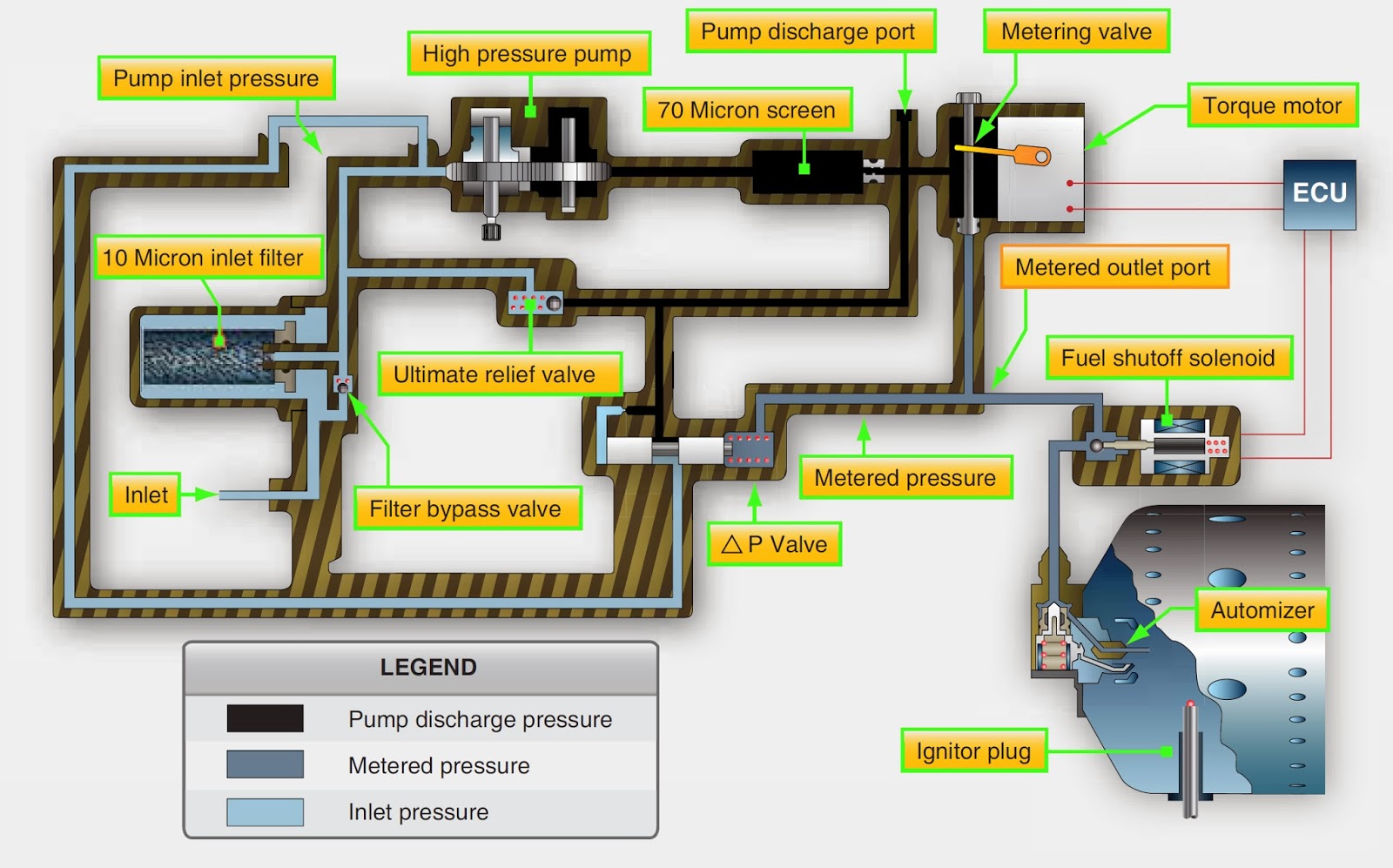
Aircraft Systems: Aircraft Turbine Engine Fuel System Requirements

Gas Turbine Diagram

2 : Schematic of a gas turbine engine (Aviation, 2004) | Download
